Assembly step 4
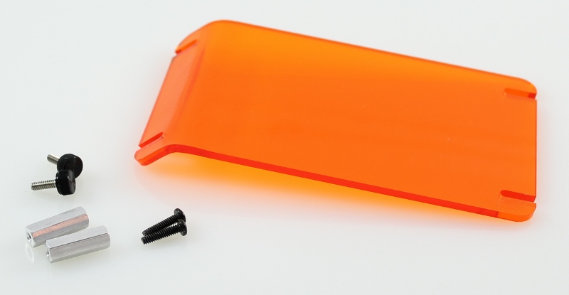
In the assembly step you will be attaching the amber lid using the remaining hardware (2 x screws, 2 x thumbscrews, 2 x standoffs). The amber lid has been designed with a horizontal edge and a curved edge so that it can be placed in two different orientations - either horizontal to the transilluminator for regular gel viewing and imaging or at a 45 degree angle for gel manipulations (i.e. cutting out bands). As with the previous steps, the following instructions apply to all versions of the transilluminator (mini, midi and large).
Attaching the amber lid
Final hardware steps
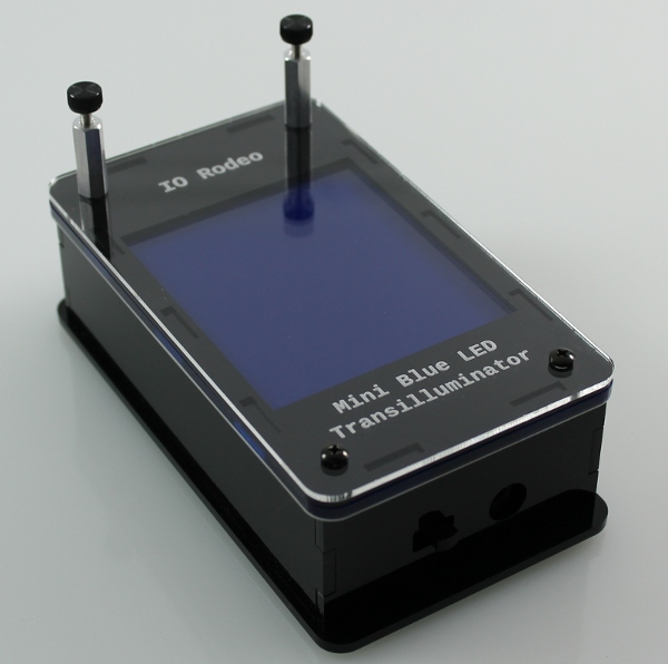
- Orient the transilluminator enclosure so that the front end facing you is the side with the DC Jack and Switch.
- In the front end of the transilluminator, screw in the two remaining screws.
- In the back end place of the transilluminator, screw the two remaining standoffs onto the threaded studs.
- Finally, screw in the two thumbscrews into the standoffs.
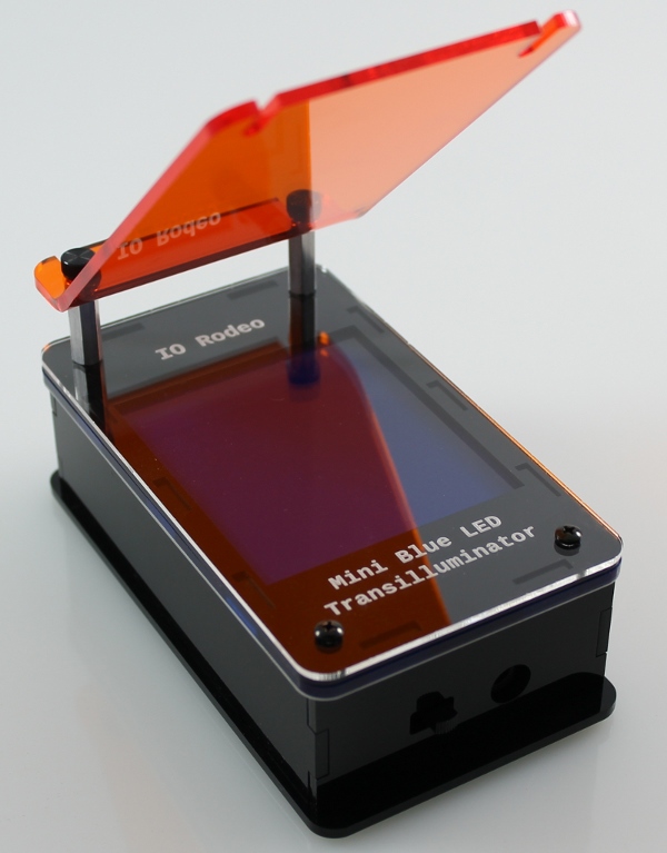
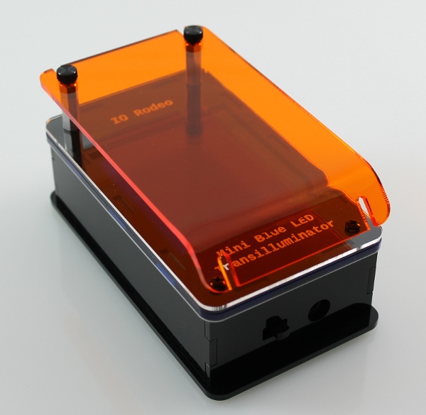
Attach the amber lid
Whether placing the amber lid in the horizontal position or at a 45 degree angle, in both cases insert the side of the amber lid into the two thumbscrews and tighten down into place. Choose the curved edge for the angled lid position and the straight edge for the horizontal position.
Horizontal position
45-degree angled position