PCB design and schematic
The design for the electrophoresis power supply PCB is based on the Maxim high efficiency MAX1771 step-up DC-DC controller and boosts a 15V input, from an external wall-wart power supply, to an adjustable 25-100V output. The power supply uses a switch-mode design in a step-up (boost) topology - as shown in figure 2 of Maxim’s An Introduction to switch-mode power supplies. An important source of inspiration for this design was the open source 150-220V Nixie tube power supply designed by Nick de Smith.
A schematic of the power supply design.
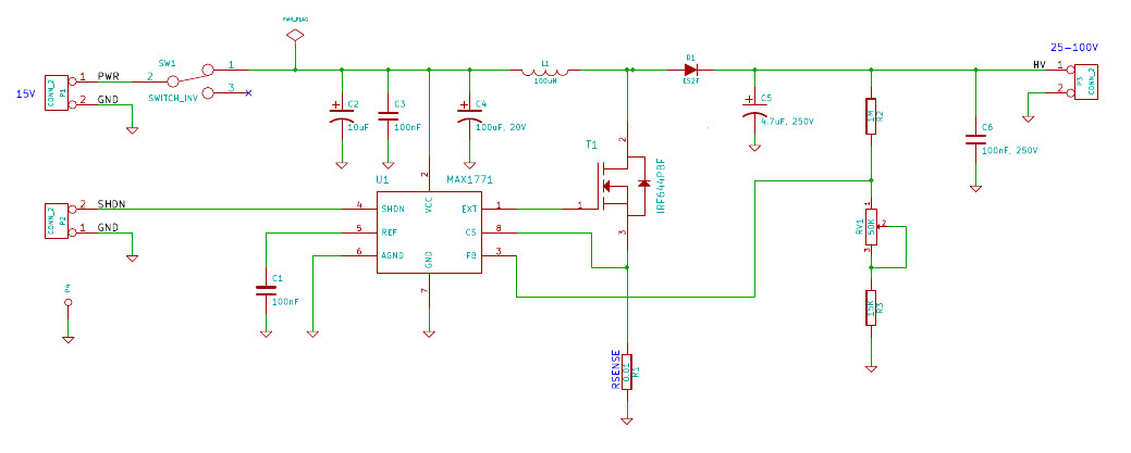
The fundamental components of the design are the MAX1771 DC-DC controller (U1), a MOSFET switch (T1), an inductor (L1), a diode (D1) and an output capacitor (C5). In the design the controller regulates the output voltage via a Pulse-Frequency Modulated (PFM) signal applied to the gate of the MOSFET. When this signal is high the MOSFET switch is turned on and when this signal is low the MOSFET is turned off. The controller adjusts the pulse rate of the PFM signal, based on feedback from the output, in order to maintain a constant output voltage. The PFM signal divides the operating cycle of the power supply into charging and discharging phases. During the charging phase, the MOSFET is turned on and energy is stored in the inductor, the diode is reverse biased preventing current flow, and the load is supported by energy stored in the output capacitor. During the discharging phase the MOSFET is turned off, the diode is forward biased and energy is transferred from the inductor to the load and the output capacitor.
The magnitude of output voltage of the power supply is set using a voltage divider on the feedback from the output to the DC-DC controller. In the schematic this voltage divider consists of resistors R1, R3 and RV1. Using the values of these resistors the output voltage of the supply can be determined via the formula Vout = Vref (R2/(R3 + RV1) + 1) where Vref has a value of 1.5 V. For this design we used fixed resistors for R2 and R3 with values of 1M ohm and 15k ohm respectively. For RV1 we selected a variable resistor with 0-50k ohm range. Plugging these values into the formula above gives a theoretical output range of roughly 25-100 V.
When determining the required voltage output, we followed the recommended guidelines of 5 V/cm, where cm refers to the distance between the two electrodes. For our mini-gel system, electrode distance is 17 cm, so ideally we should run the gel at 85 V.