Assembly Step 2: Enclosure assembly
Assembly Instructions
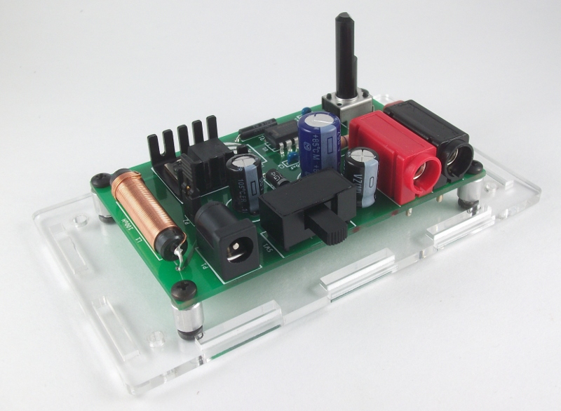
Mount the assembled PCB onto the acrylic enclosure base
Mount the assembled PCB onto the four short (1/4”) round standoffs using the four smaller (3/16”) screws and mount the PCB onto the clear acrylic base with four of the 1/4” screws.
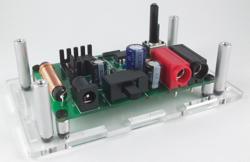
Place the four longer (1”) round standoffs in each corner
The standofs are used to secure the top and the enclosure.
Place the four sides onto the clear base
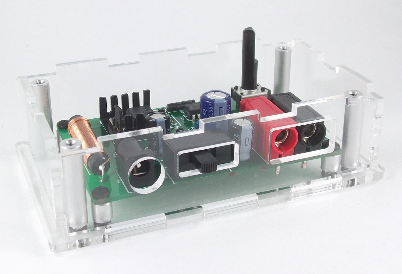
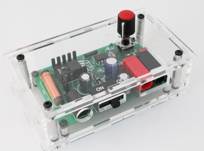
Place the top onto the case and secure with the remaining four 1/4” screws
Mount the knob onto the flat side of the potentiometer
This style of knob uses a set screw for mounting onto the potentiometer. Place the knob onto the potentiometer so that the set screw is on the same side as the flat-side of the potentiometer. Use the mini-screwdriver blade to tighten the set screw down as shown in the images below.
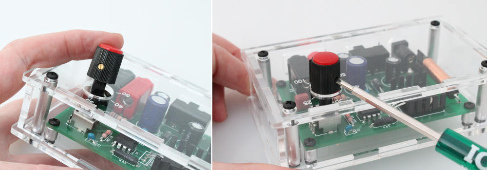
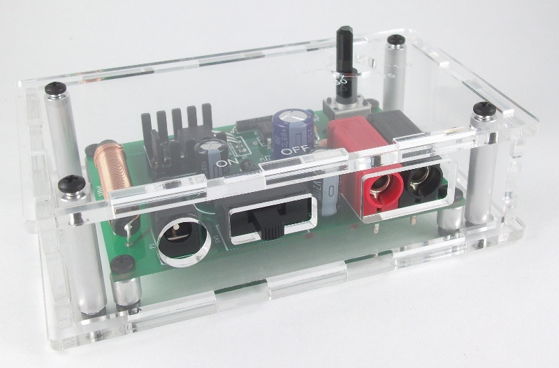
Image of the final assembled device